SSGG 7 - Continuous and Discontinuous Modelling of Fracture in Concrete Using FEM
Sign up for access to the world's latest research
AI-generated Abstract
This research addresses the modeling of fracture in concrete using Finite Element Method (FEM), analyzing both continuous and discontinuous approaches. The study highlights the necessity of incorporating microstructural characteristics into classical constitutive laws to accurately represent strain localization and size effects. Both monotonic and cyclic loading conditions are simulated, utilizing various continuum models and formulations to capture macro-crack formation and mesh-objective results.
Figures (410)


![Fig. 5.27 Relationship between calculated normalized loads: P(Ex,bt) and PAf,bt) during uniaxial tension (with /=5 mm) and ratio h/], as compared to size effect law by Bazant (2003) within: a) damage mechanics, b) elasto-plasticity (Bobinski and Tejchman 2006)](https://figures.academia-assets.com/37013038/figure_109.jpg)


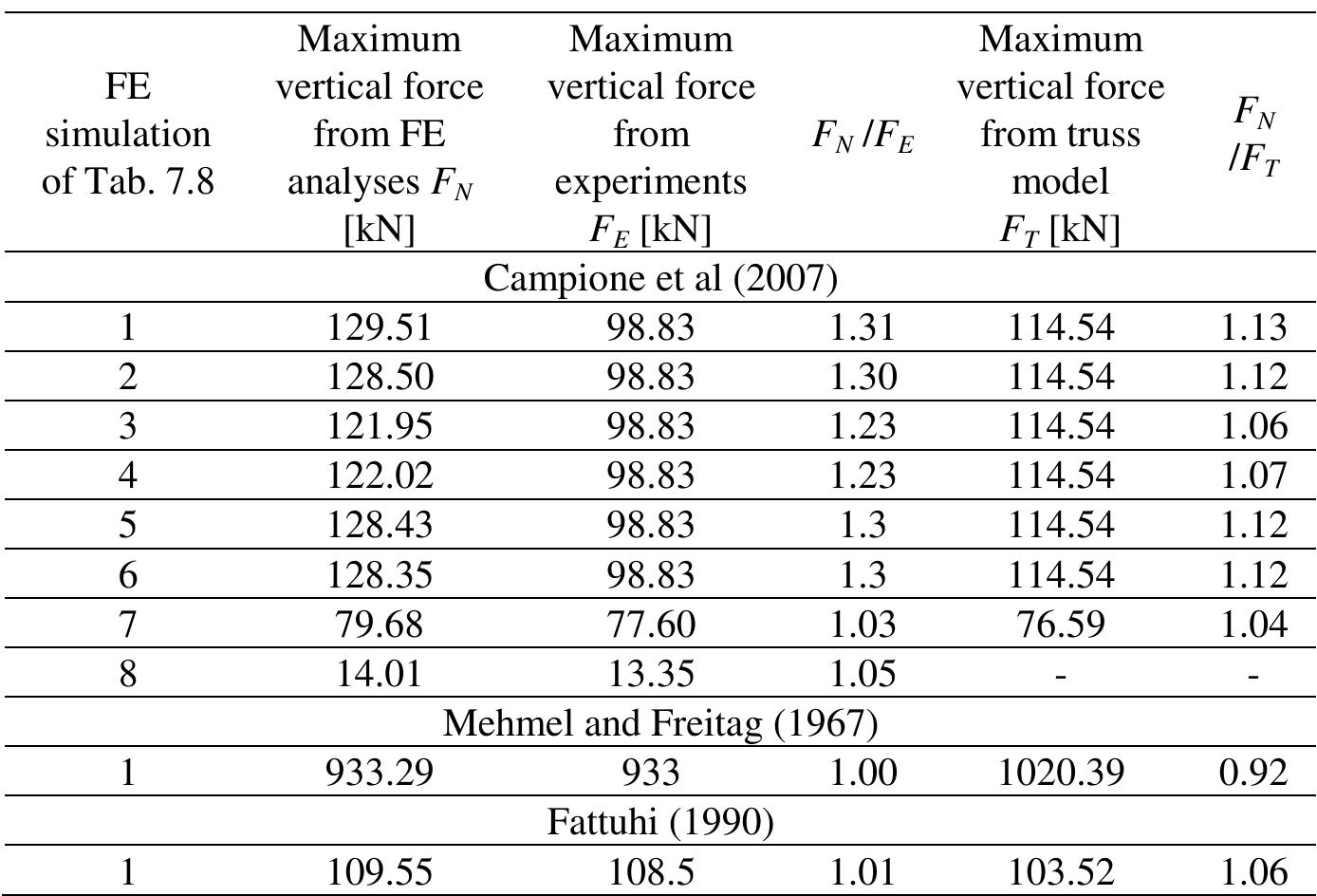
![[1] Kim and Lee (2000), [2] Hsu (1988), [3] Lloyd and Rangan (1996), [4] Bazant and Kwon (1994).](https://figures.academia-assets.com/37013038/table_014.jpg)


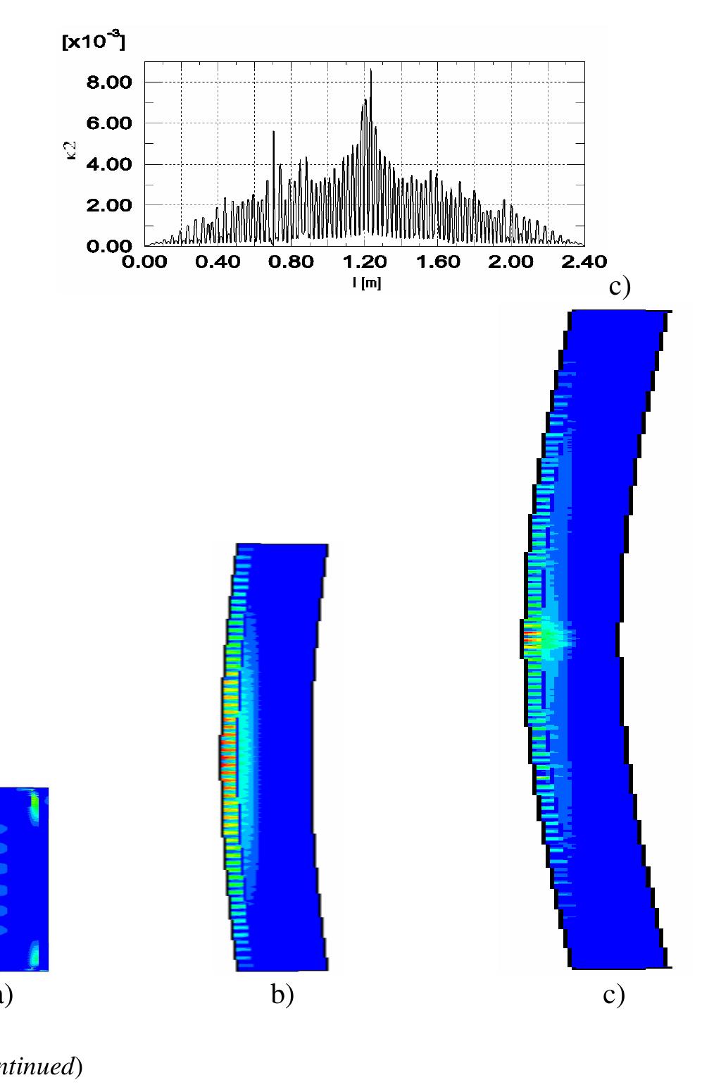
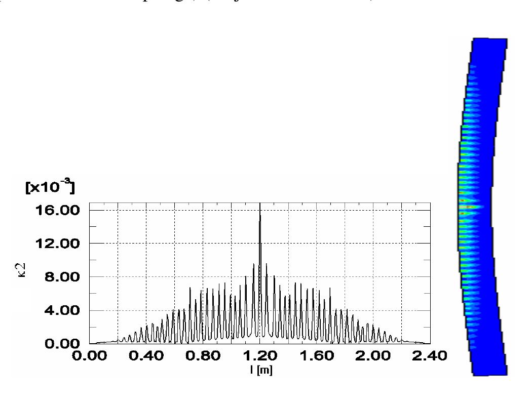
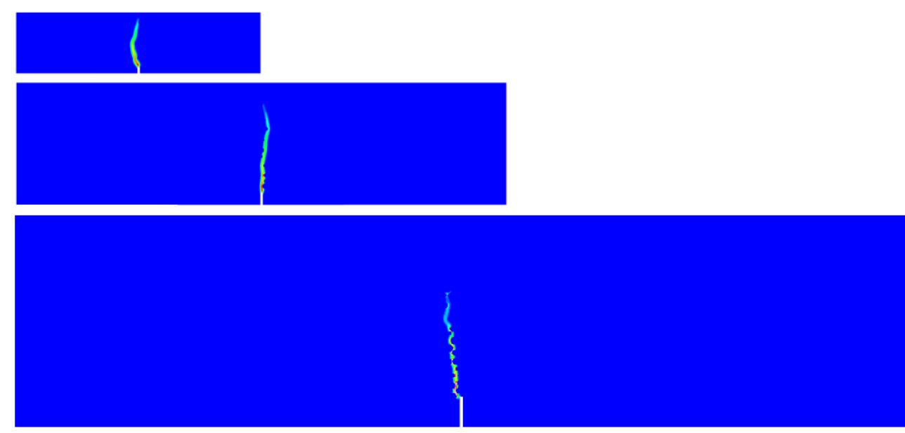
![Fig. 8.7 The correlation distances for different coefficients 2 [1/m] (Bobinski et al. 2009)](https://figures.academia-assets.com/37013038/figure_285.jpg)


![Fig. 9.23 Formation of localized zone with mean width of w,=3.5-4.0 mm directly above notch in 3 different experiments (‘a’, ‘b’ and ‘c’) with small-size notched fine-grained concrete beam 80x320x40 mm? using DIC (vertical and horizontal axes denote coordinates in [mm] and colour scales strain intensity) (Skarzynski et al. 2011) digital images taken at a constant time increment from a professional digital camera (based on displacements, strains can be calculated) (White et al. 2003). The experimental set-up and results were described in detail by Skarzynski et al. (2011). The beams of the same size were also used by Le Bellégo et al. (2003). Figure 9.23 shows the formation of a localized zone on one side of the surface of a fine-grained small-size concrete beam above the notch from laboratory tests](https://figures.academia-assets.com/37013038/figure_344.jpg)


Key takeaways
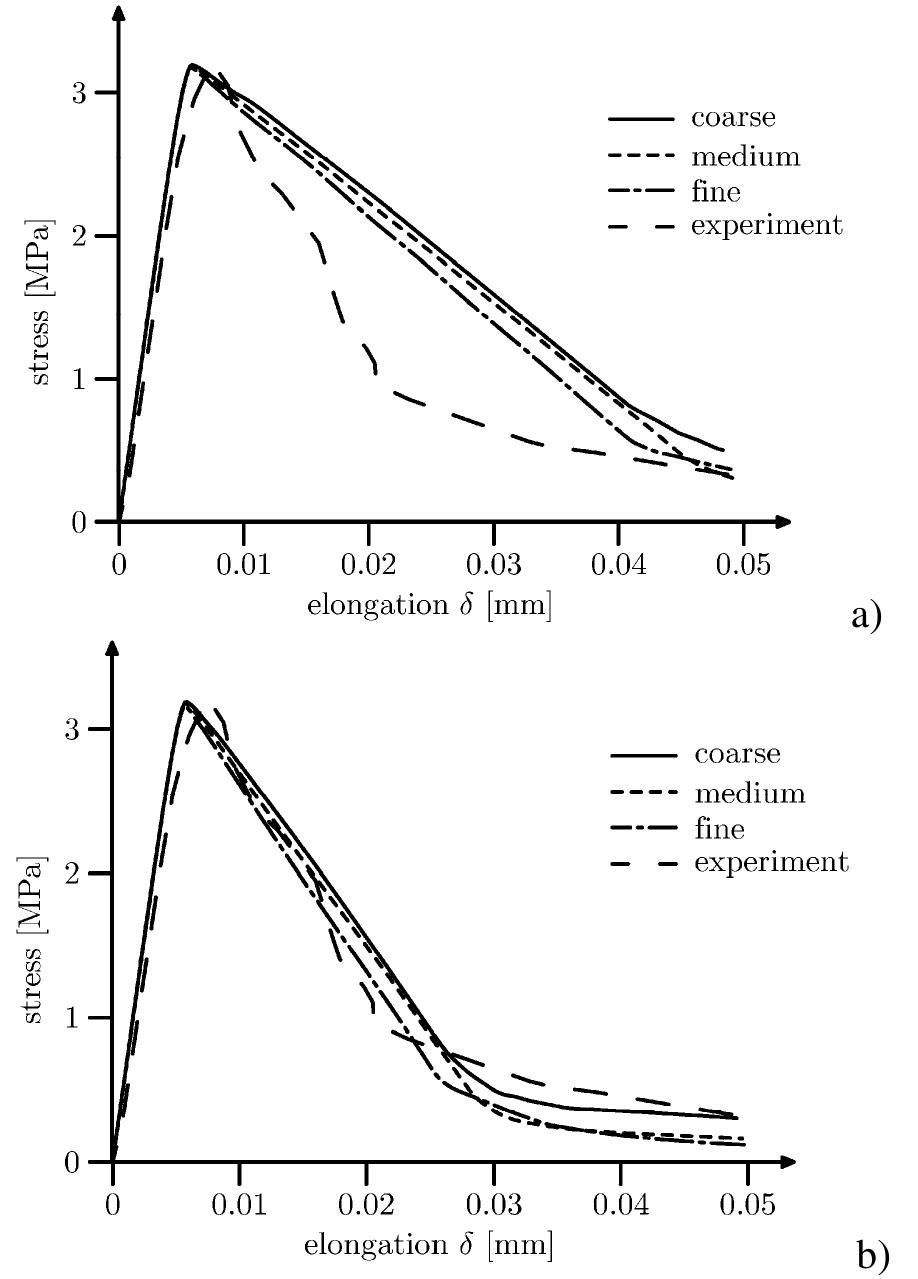
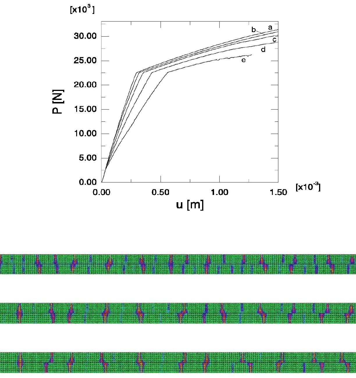
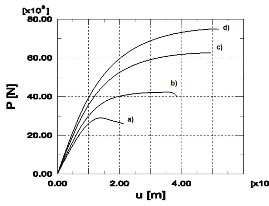
- The differences concern the height and shape of localized zones, • the FE-results are similar within two different continuum crack models, although a slightly better agreement with experiments was achieved with a damage model, • the beam strength increases mainly with increasing reinforcement ratio, characteristic length, tensile strength, fracture energy and decreasing beam size and shear span ratio.
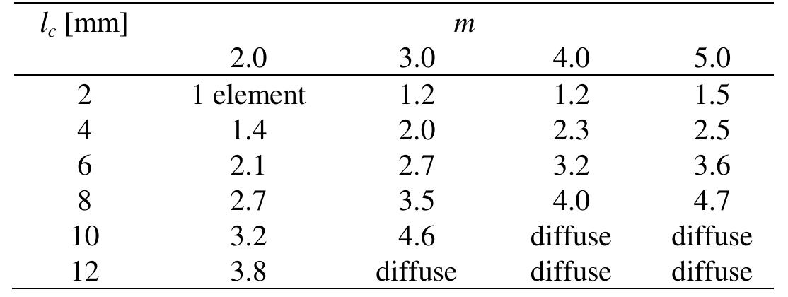
- The width is about (3-4)×l c , • the spacing of localized zones increases with increasing characteristic length l c , tensile softening modulus and decreasing fracture energy, reinforcement ratio and initial bond stiffness.
- Thus, the isotropic damage model needs improvements to describe localized shear zones in reinforced concrete elements under shear-tension failure, • the calculated spacing of localized tensile zones increased with increasing characteristic length, softening rate and beam height and decreasing fracture energy and bond stiffness.
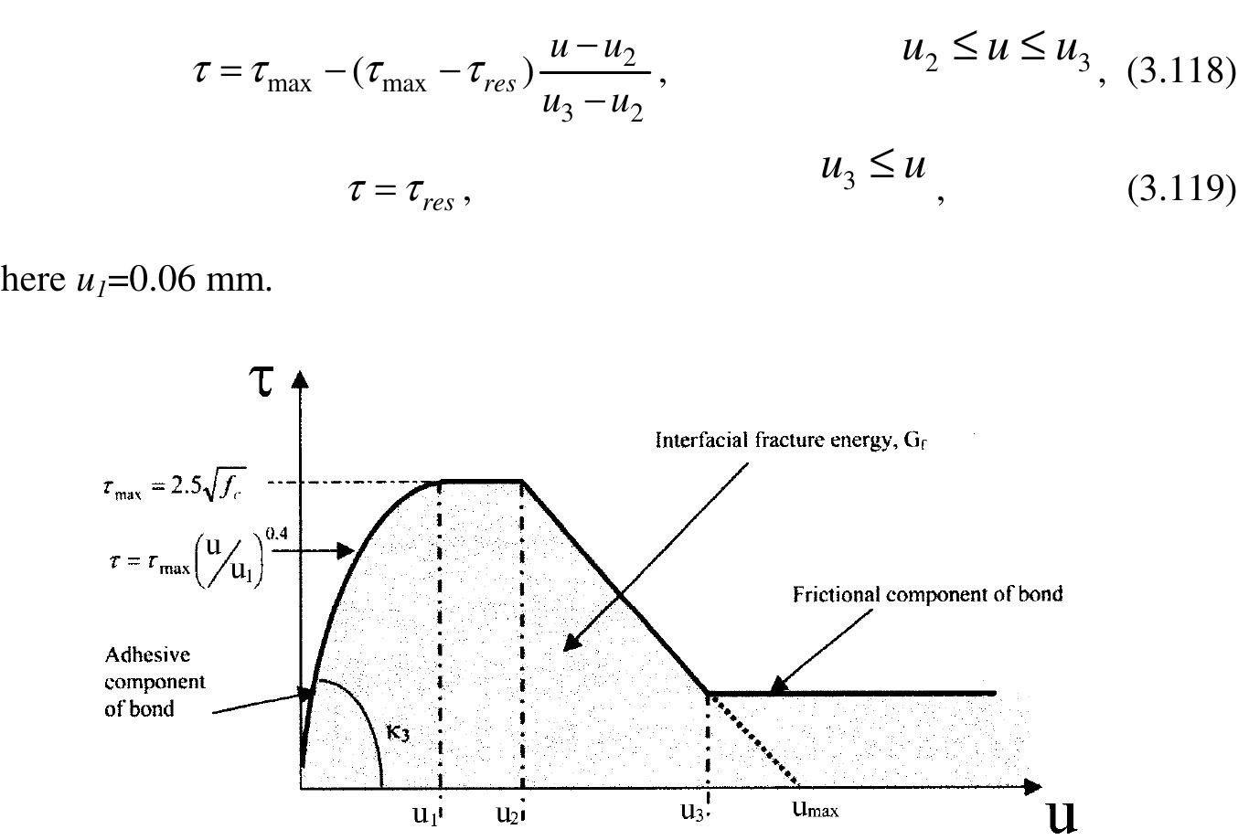
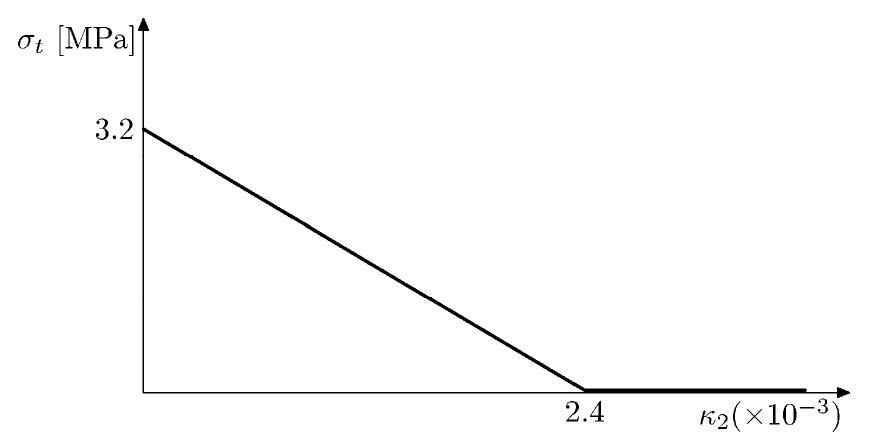
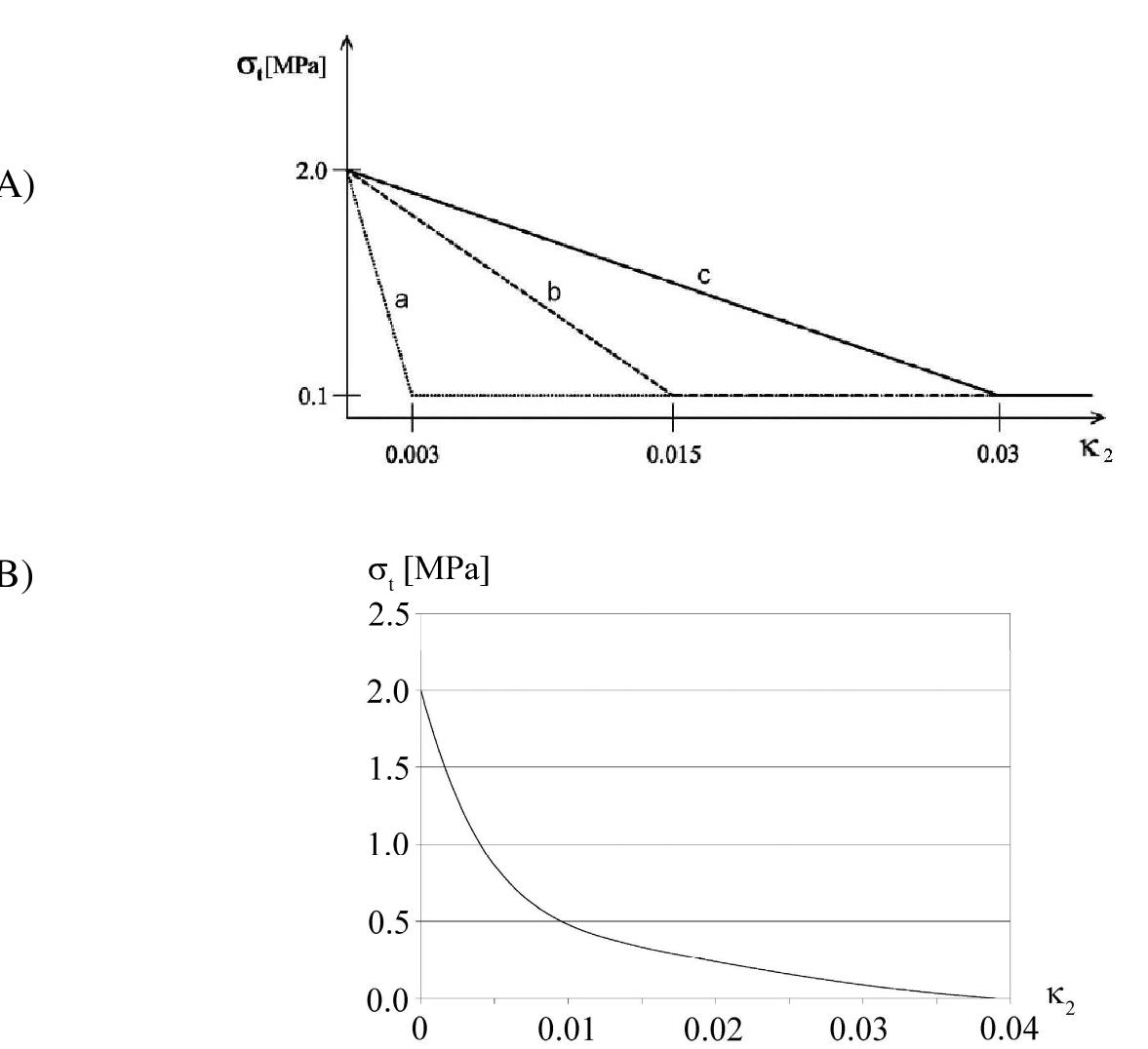
- To model the concrete softening under tension, the exponential curve by with the tensile strength of the concrete of f t =3.6 MPa was assumed (κ u =0.005 b 1 =3.0, b 2 =6.93) (Eq.
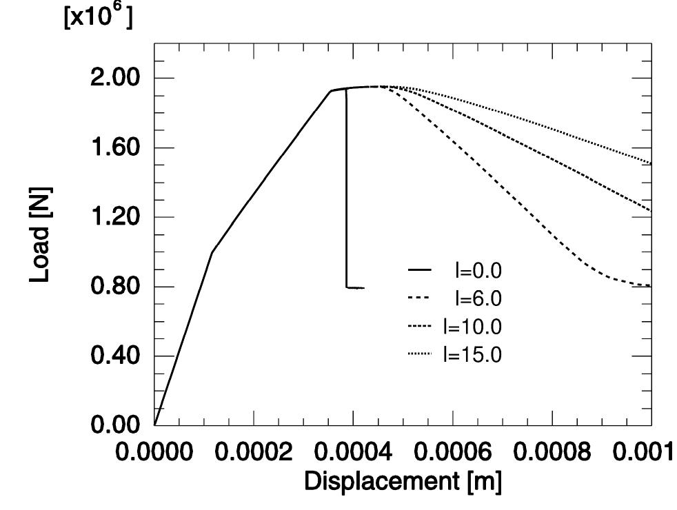
- For instance, in our other tests with large reinforced concrete beams 6.0 m long without shear reinforcement under bending, the width of a localized zone in usual concrete was about 15 mm indicating that l c =5 mm .
