Electrical installation handbook Protection, control and electrical devices
 Taner Esen
Sign up for access to the world's latest research
Abstract
In order to ensure the proper function in such environments, the shipping registers require that the apparatus has to be tested according to specific type approval tests, the most significant of which are vibration, dynamic inclination, humidity and dry-heat tests.
Figures (502)


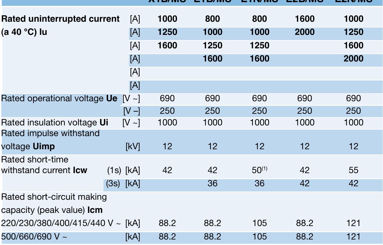
![Rated operational voltage Ue [V]](https://figures.academia-assets.com/52858715/table_066.jpg)


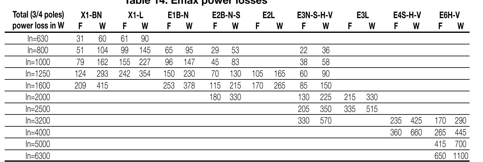
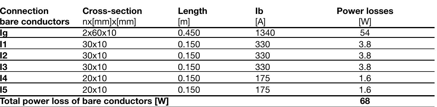


![Thus, the total power loss inside the enclosure is: P = 784 [W]
Here below the power losses for each connection:](https://figures.academia-assets.com/52858715/table_179.jpg)


![Table 1: Resistance values [Q/km] of single-core and multi-core
cables in copper and aluminium at 80 °C](https://figures.academia-assets.com/52858715/table_215.jpg)

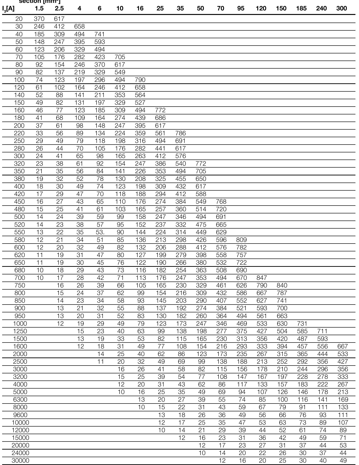
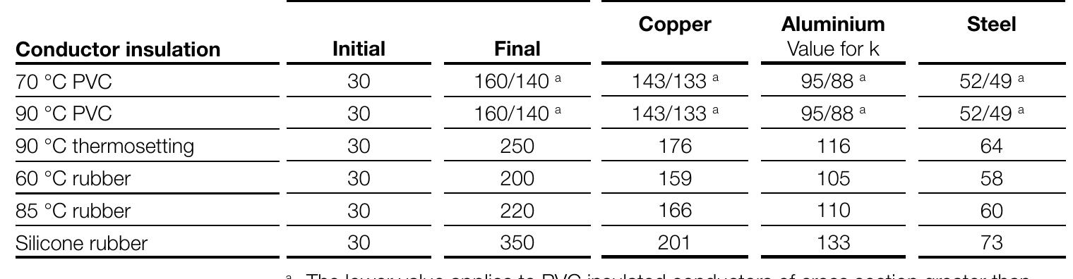
![The formula (1) must be verified along the whole length of the cable. Due to the
shape of the specific let-through energy curve of a circuit breaker, it is generally
sufficient to verify formula (1) only for the maximum and minimum short-circuit
current that may affect the cable. The maximum value is normally the value
of the three-phase short-circuit current at the beginning of the line, while the
minimum value is the value of the phase to neutral short-circuit current (phase
to phase if the neutral conductor is not distributed) or phase to earth at the
end of the cable.
Table 2: Maximum withstood energy for cables k? S? [(kA)? s]](https://figures.academia-assets.com/52858715/table_216.jpg)


![Short-circuit power S,__, [MVA]
knet
Net voltage U, [kV]
Generator](https://figures.academia-assets.com/52858715/table_313.jpg)


Key takeaways
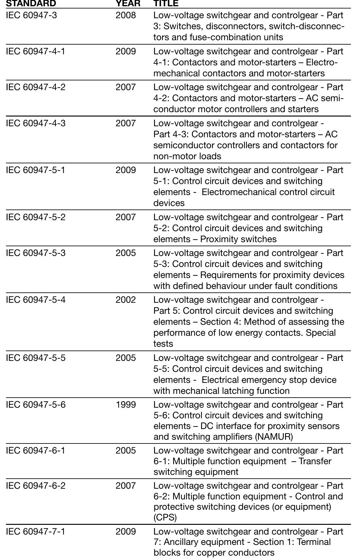
- The utilization category of a circuit-breaker shall be stated with reference to whether or not it is specifically intended for selectivity by means of an intentional time delay with respect to other circuit-breakers in series on the load side, under short-circuit conditions (Table 4 IEC 60947-2).
- The tables shown give the short-circuit current value (in kA) for which the backup protection is verified for the chosen circuit-breaker combination, at voltages from 240 up to 415 V. These tables cover all the possible combinations between ABB SACE moulded-case circuit-breakers Tmax XT/Tmax T and those between the above mentioned circuit-breakers and ABB MCBs.
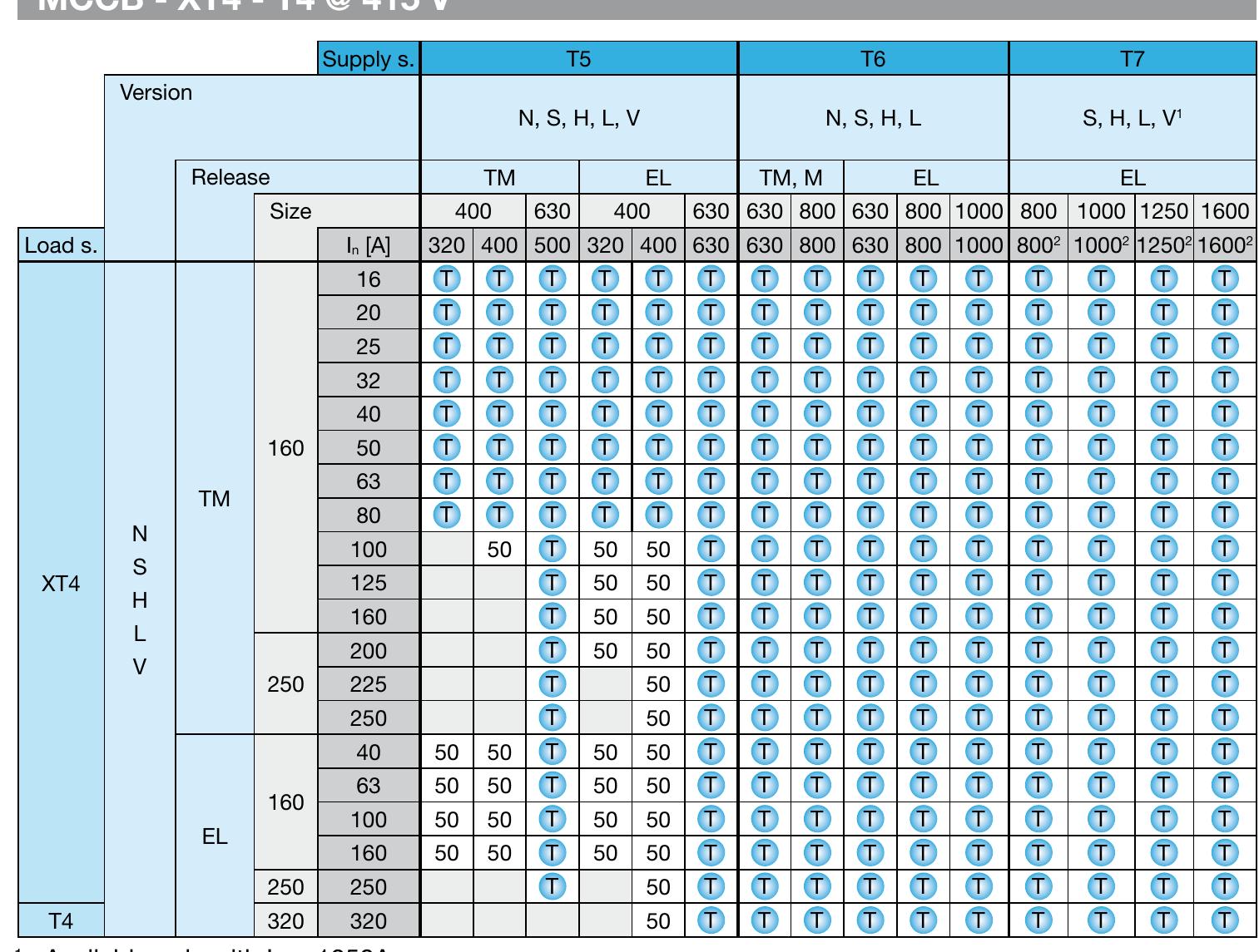
- The tables shown give the values of the short-circuit current (in kA) for which back-up protection is verified by the pre-selected combination of circuit-breaker and switch disconnector, for voltages between 380 and 415 V. The tables cover the possible combinations of moulded-case circuit-breakers in the SACE Tmax XT and Tmax T series, with the switch disconnectors detailed above.
- • the neutral conductor is protected against short-circuit by a protective device fitted upstream; • the circuit is protected by a residual current device with rated residual current lower than 0.15 times the current carrying capacity of the corresponding neutral conductor.
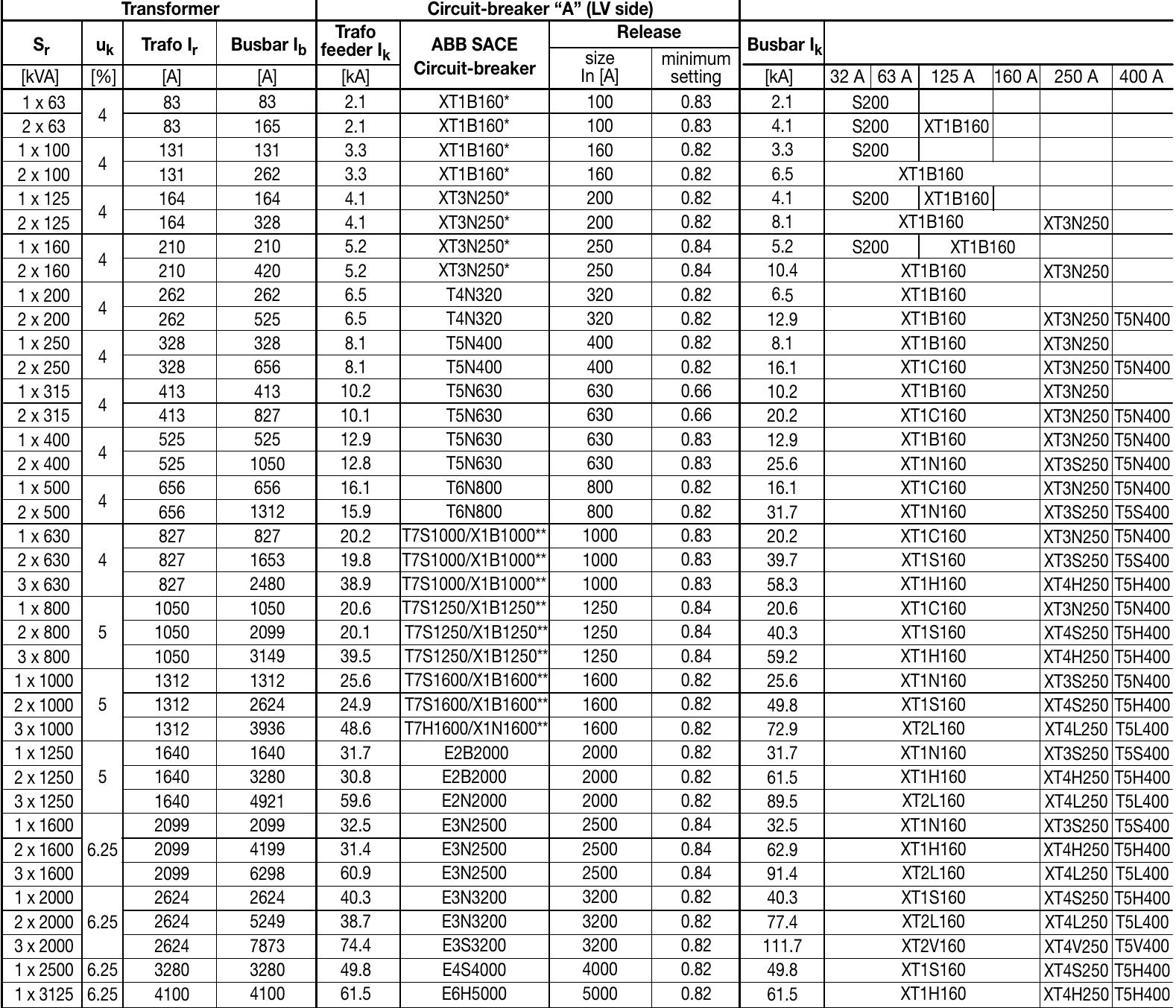
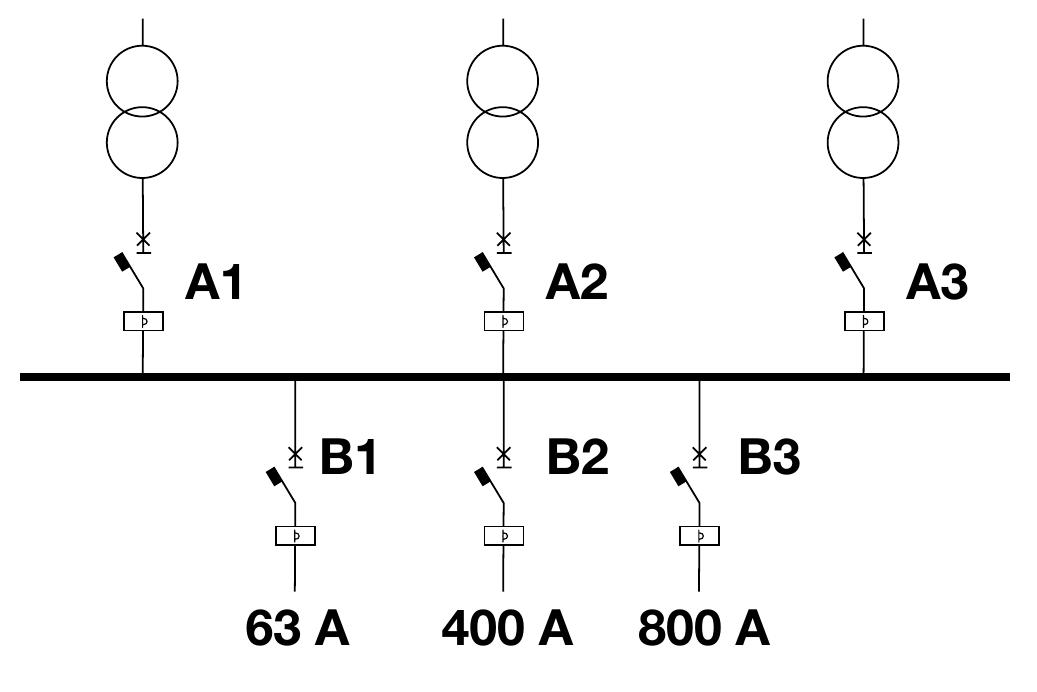
- • trafo I r (909 A) is the current that flows through the transformer circuitbreakers; • busbar I b (2727 A) is the maximum current that the transformers can supply; • trafo feeder I k (42.8 kA) is the value of the short-circuit current to consider for the choice of the breaking capacity of each of the transformer circuit-breakers; • T7S1000 or X1N1000 is the size of the transformer circuit-breaker; • In (1000 A) is the rated current of the transformer circuit-breaker (electronic release chosen by the user); • the minimum value 0.91 indicate the minimum settings of the L function of the electronic releases for CBs T7S1000 and X1N1000.
