Electrical installation handbook Protection, control and electrical devices
 Kushtrim Mala
Sign up for access to the world's latest research
Abstract
study
Figures (502)


![Rated operational voltage Ue [V]](https://figures.academia-assets.com/52332606/table_066.jpg)


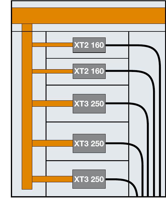


![Thus, the total power loss inside the enclosure is: P = 784 [W] Here below the power losses for each connection:](https://figures.academia-assets.com/52332606/table_179.jpg)


![Table 1: Resistance values [Q/km] of single-core and multi-core cables in copper and aluminium at 80 °C](https://figures.academia-assets.com/52332606/table_215.jpg)

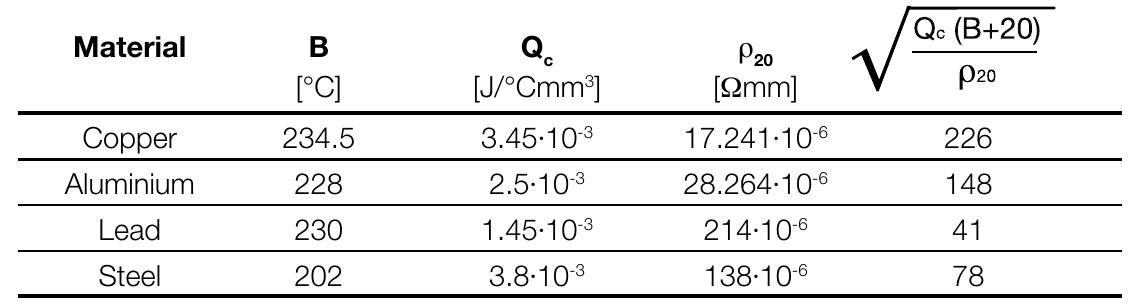
![The formula (1) must be verified along the whole length of the cable. Due to the shape of the specific let-through energy curve of a circuit breaker, it is generally sufficient to verify formula (1) only for the maximum and minimum short-circuit current that may affect the cable. The maximum value is normally the value of the three-phase short-circuit current at the beginning of the line, while the minimum value is the value of the phase to neutral short-circuit current (phase to phase if the neutral conductor is not distributed) or phase to earth at the end of the cable. Table 2: Maximum withstood energy for cables k? S? [(kA)? s]](https://figures.academia-assets.com/52332606/table_216.jpg)


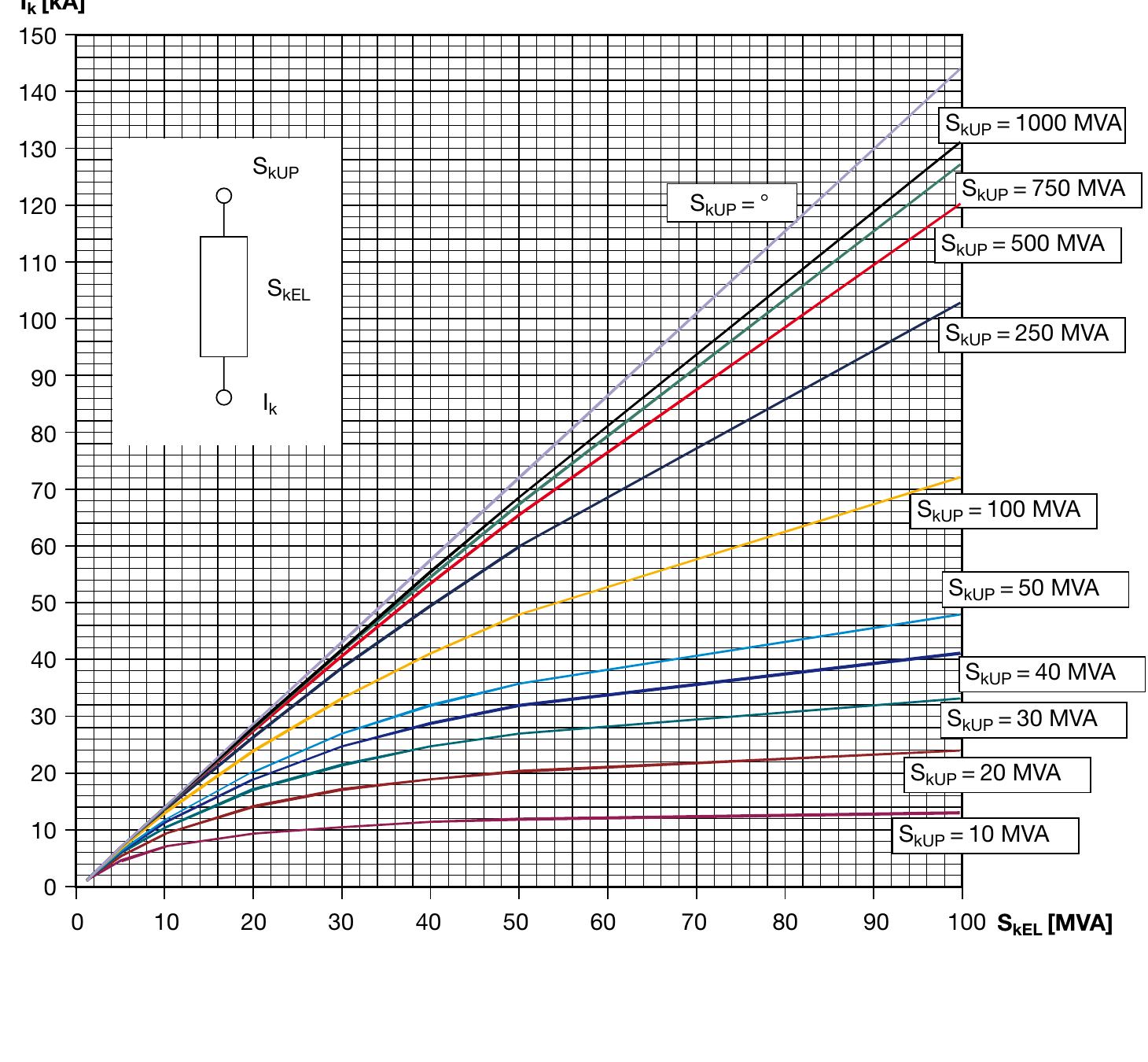
![Short-circuit power S,__, [MVA] knet Net voltage U, [kV] Generator](https://figures.academia-assets.com/52332606/table_313.jpg)


Key takeaways
- The utilization category of a circuit-breaker shall be stated with reference to whether or not it is specifically intended for selectivity by means of an intentional time delay with respect to other circuit-breakers in series on the load side, under short-circuit conditions (Table 4 IEC 60947-2).
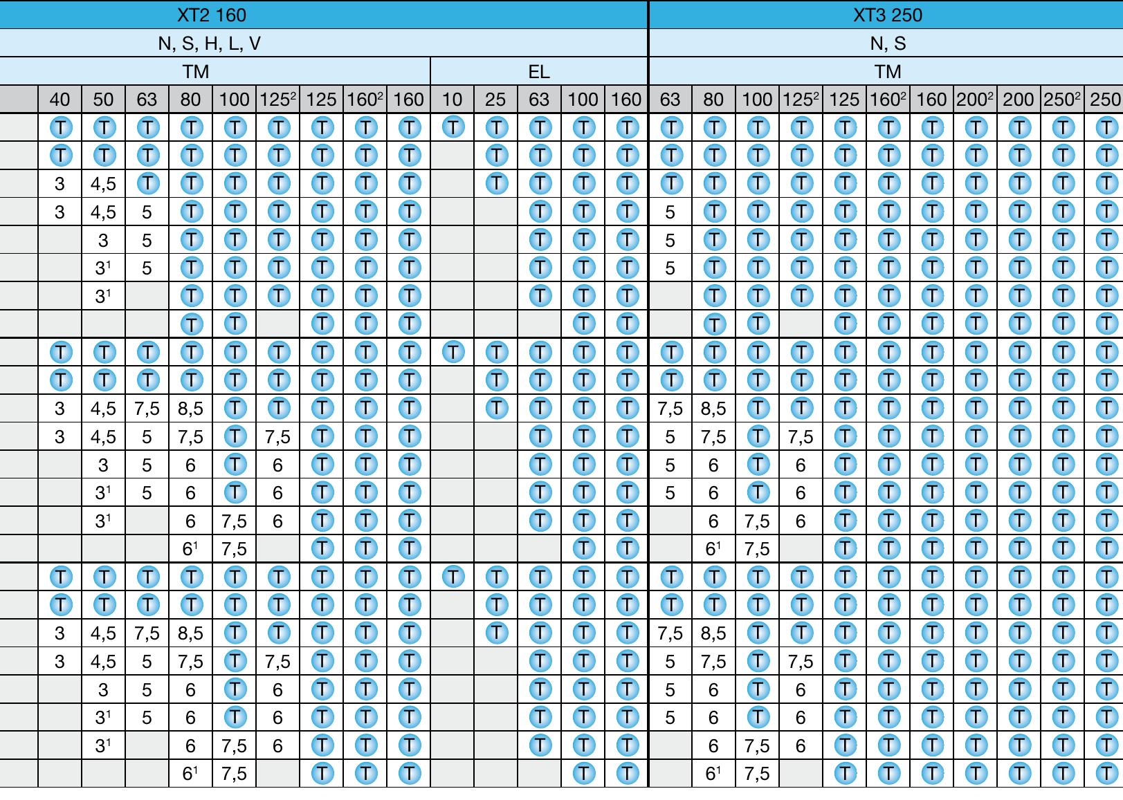
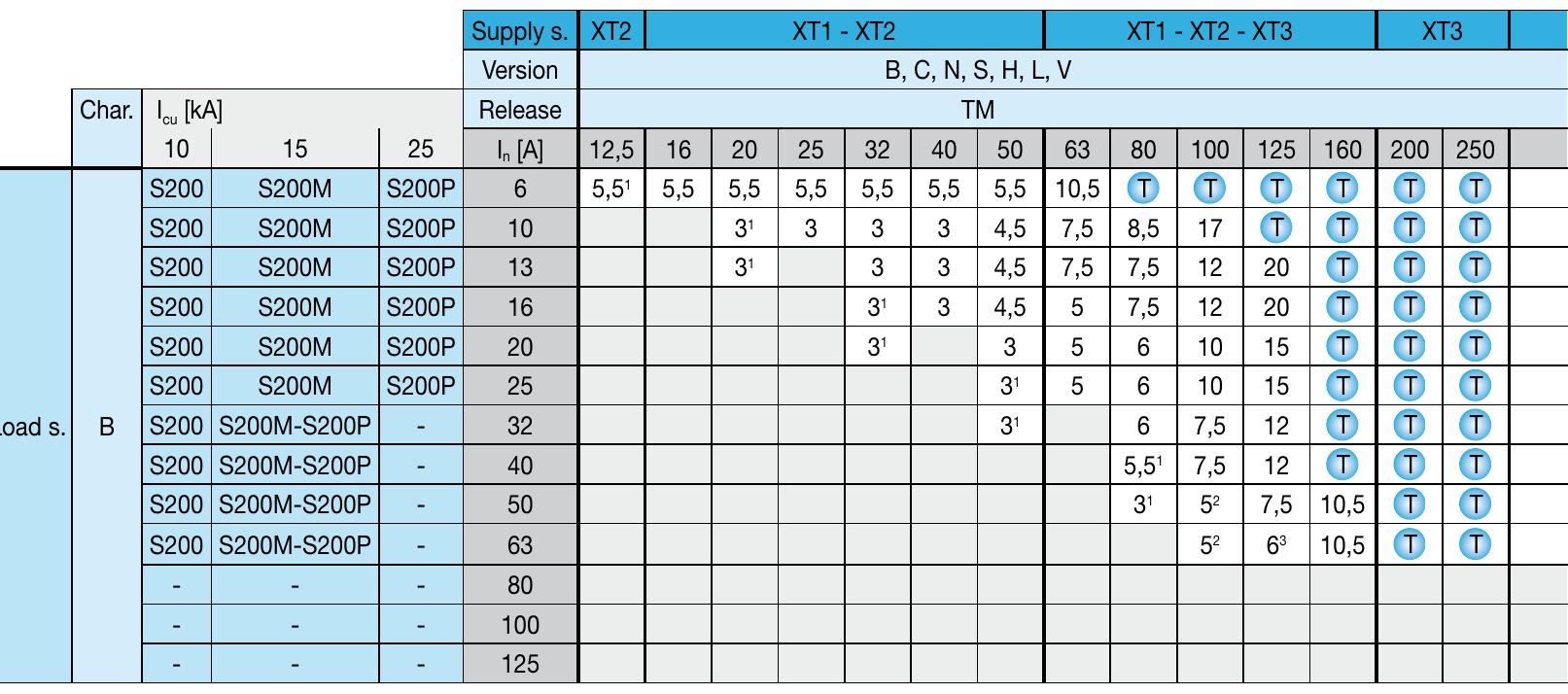
- The tables shown give the short-circuit current value (in kA) for which the backup protection is verified for the chosen circuit-breaker combination, at voltages from 240 up to 415 V. These tables cover all the possible combinations between ABB SACE moulded-case circuit-breakers Tmax XT/Tmax T and those between the above mentioned circuit-breakers and ABB MCBs.
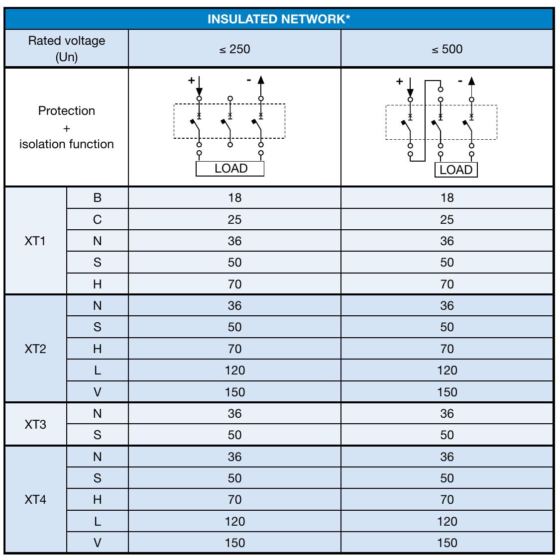
- The tables shown give the values of the short-circuit current (in kA) for which back-up protection is verified by the pre-selected combination of circuit-breaker and switch disconnector, for voltages between 380 and 415 V. The tables cover the possible combinations of moulded-case circuit-breakers in the SACE Tmax XT and Tmax T series, with the switch disconnectors detailed above.
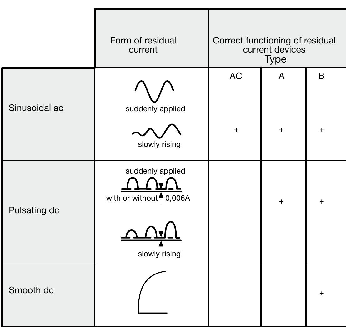
- • the neutral conductor is protected against short-circuit by a protective device fitted upstream; • the circuit is protected by a residual current device with rated residual current lower than 0.15 times the current carrying capacity of the corresponding neutral conductor.
- • trafo I r (909 A) is the current that flows through the transformer circuitbreakers; • busbar I b (2727 A) is the maximum current that the transformers can supply; • trafo feeder I k (42.8 kA) is the value of the short-circuit current to consider for the choice of the breaking capacity of each of the transformer circuit-breakers; • T7S1000 or X1N1000 is the size of the transformer circuit-breaker; • In (1000 A) is the rated current of the transformer circuit-breaker (electronic release chosen by the user); • the minimum value 0.91 indicate the minimum settings of the L function of the electronic releases for CBs T7S1000 and X1N1000.
